User:Ashmanskas/p364/verilog notes
From LaPET electronics
Contents |
A few more notes on Verilog
To save you the hassle of reading long sections of the Verilog book chapters I handed out, here is my latest attempt at a brief Verilog synopsis.
- several examples adapted from CIS 371 notes: http://www.seas.upenn.edu/~cis371/
- a decent online source of Verilog tutorial material is http://www.asic-world.com/verilog/
Modules
A Verilog design consists of a set of modules, connected hierarchically.
You can think of a module as a schematic diagram. Your complete circuit will have a top-level module, as your circuit would have a top-level schematic diagram. In that module, you will often create instances of other modules. Similarly, your schematic diagram will contain several components, each of which can be described by its own schematic diagram. The components that you place on your schematic or instantiate in your module are connected with wires.
Consider a multiplexer, (or mux for short) which chooses between input A and input B, depending on the value of input S (for "select"). The multiplexer's output is the value of the chosen input. Schematically, you draw a mux like the figure on the left, and can implement it as the figure on the right:
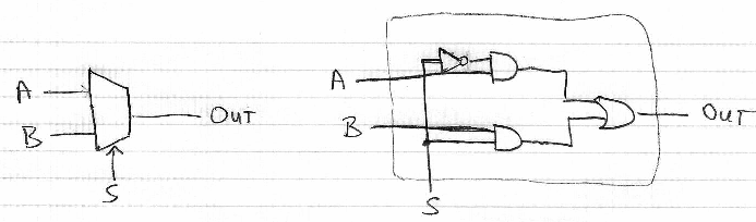
Here is a Verilog implementation that most closely corresponds to the right-hand drawing:
module mux2to1 (
    input  wire S, A, B,
    output wire OUT
);
    wire notS, AandnotS, BandS;
    not (notS, S);
    and (AandnotS, A, notS);
    and (BandS, B, S);
    or  (OUT, AandnotS, BandS);
endmodule
In the above example, we used the Verilog built-ins and, or, and not.
Operators
Verilog also contains C-like operators that achieve the above result more concisely:
module mux2to1 (
    input  wire S, A, B,
    output wire OUT
);
    wire notS, AandnotS, BandS;
    assign notS = ~S;
    assign AandnotS = A & notS;
    assign BandS = B & S;
    assign OUT = AandnotS | BandS;
endmodule
The wire statement creates a new wire. The assign statement connects an existing wire. The input and output ports of a module are also (usually) wires. To make things a bit more concise, it is possible to create a new wire and to connect it in the same statement, as follows:
module mux2to1 (
    input  wire S, A, B,
    output wire OUT
);
    wire notS = ~S;
    wire AandnotS = A & notS;
    wire BandS = B & S;
    assign OUT = AandnotS | BandS;
endmodule
Finally, we can eliminate the internal wires by combining several Verilog operators in a single expression:
module mux2to1 (
    input  wire S, A, B,
    output wire OUT
);
    assign OUT = (A & ~S) | (B & S);
endmodule
If you are a C programmer, you will appreciate Verilog's ternary operator, ?: , shown below. (If the first expression (S) is true, the ternary operator evaluates to the second expression (B); otherwise it evaluates to the third expression (A). This is the C-language version of a multiplexer.)
module mux2to1 (
    input  wire S, A, B,
    output wire OUT
);
    assign OUT = S ? B : A;
endmodule
Incidentally, just as in C, there are both bitwise operators (&, |, ~) and logical operators (&&, ||, !) for and, or, and not. Bitwise xor is the ^ operator.
Vectors
Just as a more complex circuit can be built up from simpler circuits, you can build up more complex modules from simpler ones. For instance, a four-bit-wide mux can be made from four single-bit multiplexers. Notice that when you instantiate a module within another module, you must name each instance. The example below contains four instances of mux2to1. They are named mux0, mux1, mux2, and mux3. Notice also that you can declare wire vectors that are wider than a single wire. (In this example, A, B, and OUT are all four bits wide. As in C, the usual convention is to start counting from zero, though other numberings are possible in Verilog.)
module mux2to1_4bit (
    input  wire       S,
    input  wire [3:0] A,
    input  wire [3:0] B,
    output wire [3:0] OUT
);
    mux2to1 mux0 (S, A[0], B[0], OUT[0]);
    mux2to1 mux1 (S, A[1], B[1], OUT[1]);
    mux2to1 mux2 (S, A[2], B[2], OUT[2]);
    mux2to1 mux3 (S, A[3], B[3], OUT[3]);
endmodule
The above example is a bit contrived, to show you how a hierarchy of modules can be instantiated. If you really just want a four-bit mux, you can code it more simply like this:
module mux2to1_4bit (
    input  wire       S,
    input  wire [3:0] A,
    input  wire [3:0] B,
    output wire [3:0] OUT
);
    assign OUT = S ? B : A;
endmodule
Parameters
If you want to generalize the mux to N bits wide, you can use a parameter, as follows. (Here we give the parameter N a default value of 1.)
module mux2to1_Nbit #(parameter N=1)
(
    input  wire         S,
    input  wire [N-1:0] A,
    input  wire [N-1:0] B,
    output wire [N-1:0] OUT
);
    assign OUT = S ? B : A;
endmodule
To instantiate this module (within some other module whose details we omit),
wire [3:0] inputA, inputB, muxout;
mux2to1_Nbit #(4) mymux (S, inputA, inputB, muxout);
Arguments by name vs. by position
Note that it is possible (and much less error prone, hence strongly encouraged) to specify arguments by name rather than by position when you instantiate a module. The following is equivalent to the previous example, but completely avoids the trap of accidentally writing the arguments in the wrong order:
wire [3:0] inputA, inputB, muxout;
mux2to1_Nbit #(.N(4)) mymux (.S(S), .A(inputA), .B(inputB), .OUT(muxout));
Synchronous logic: flip-flop
Here is a module that implements a D-type flip-flop:
module dff (
    input  wire clk,
    input  wire d,
    output wire q
);
    reg qreg=0;  // initial value 0 has no effect on synthesis, but makes simulation start in known state
    always @ (posedge clk) begin
        qreg <= d;
    end
    assign q = qreg;
endmodule
Adding an enable input makes a D-flop much more useful for applications such as counters:
module dffe (
    input  wire clk,
    input  wire ena,
    input  wire d,
    output wire q
);
    reg qreg=0;
    always @ (posedge clk) begin
        if (ena) qreg <= d;
    end
    assign q = qreg;
endmodule
Counter
Now we can build up a six-bit synchronous counter, as follows:
module counter (
    input  wire       clk,
    output wire [5:0] q
);
    dffe ff0 (.clk(clk), .q(q[0]), .d(~q[0]), .ena(1));
    dffe ff1 (.clk(clk), .q(q[1]), .d(~q[1]), .ena(q[0]==1));
    dffe ff2 (.clk(clk), .q(q[2]), .d(~q[2]), .ena(q[1:0]==3));
    dffe ff3 (.clk(clk), .q(q[3]), .d(~q[3]), .ena(q[2:0]==7));
    dffe ff4 (.clk(clk), .q(q[4]), .d(~q[4]), .ena(q[3:0]==15));
    dffe ff5 (.clk(clk), .q(q[5]), .d(~q[5]), .ena(q[4:0]==31));
endmodule
By the way, you may find it more elegant to write 1, 3, 7, 15, 31 in binary:
module counter (
    input  wire       clk,
    output wire [5:0] q
);
    dffe ff0 (.clk(clk), .q(q[0]), .d(~q[0]), .ena(1));
    dffe ff1 (.clk(clk), .q(q[1]), .d(~q[1]), .ena(q[0]=='b1));
    dffe ff2 (.clk(clk), .q(q[2]), .d(~q[2]), .ena(q[1:0]=='b11));
    dffe ff3 (.clk(clk), .q(q[3]), .d(~q[3]), .ena(q[2:0]=='b111));
    dffe ff4 (.clk(clk), .q(q[4]), .d(~q[4]), .ena(q[3:0]=='b1111));
    dffe ff5 (.clk(clk), .q(q[5]), .d(~q[5]), .ena(q[4:0]=='b11111));
endmodule
or in hexadecimal:
module counter (
    input  wire       clk,
    output wire [5:0] q
);
    dffe ff0 (.clk(clk), .q(q[0]), .d(~q[0]), .ena(1));
    dffe ff1 (.clk(clk), .q(q[1]), .d(~q[1]), .ena(q[0]=='h1));
    dffe ff2 (.clk(clk), .q(q[2]), .d(~q[2]), .ena(q[1:0]=='h3));
    dffe ff3 (.clk(clk), .q(q[3]), .d(~q[3]), .ena(q[2:0]=='h7));
    dffe ff4 (.clk(clk), .q(q[4]), .d(~q[4]), .ena(q[3:0]=='hf));
    dffe ff5 (.clk(clk), .q(q[5]), .d(~q[5]), .ena(q[4:0]=='h1f));
endmodule
You can also flip the bits and compare with zero:
module counter (
    input  wire       clk,
    output wire [5:0] q
);
    dffe ff0 (.clk(clk), .q(q[0]), .d(~q[0]), .ena(1));
    dffe ff1 (.clk(clk), .q(q[1]), .d(~q[1]), .ena(~q[0]==0));
    dffe ff2 (.clk(clk), .q(q[2]), .d(~q[2]), .ena(~q[1:0]==0));
    dffe ff3 (.clk(clk), .q(q[3]), .d(~q[3]), .ena(~q[2:0]==0));
    dffe ff4 (.clk(clk), .q(q[4]), .d(~q[4]), .ena(~q[3:0]==0));
    dffe ff5 (.clk(clk), .q(q[5]), .d(~q[5]), .ena(~q[4:0]==0));
endmodule
N-bit-wide D-type flip-flop
Just as we made an N-bit-wide mux above, we can make an N-bit-wide flip-flop, whose desired width is passed as a parameter:
module dffe_Nbit #(parameter N=1)
(
    input  wire         clk,
    input  wire         ena,
    input  wire [N-1:0] d,
    output wire [N-1:0] q
);
    reg [N-1:0] qreg=0;
    always @ (posedge clk) begin
        if (ena) qreg <= d;
    end
    assign q = qreg;
endmodule
Simplified counter
Using dffe_Nbit, we can simplify the six-bit counter example:
module counter (
    input  wire       clk,
    output wire [5:0] q
);
    wire [5:0] ff_data = q+1;
    dffe_Nbit #(.N(6)) ff (.clk(clk), .q(q), .ena(1), .d(ff_data));
endmodule
Since ff_data is only used in one place, we can shorten this more:
module counter (
    input  wire       clk,
    output wire [5:0] q
);
    dffe_Nbit #(.N(6)) ff (.clk(clk), .q(q), .ena(1), .d(q+1));
endmodule
More experienced Verilog coders would implement a counter as a single module, as follows, but I think you will find the above counter easier to understand. The compiler will produce the same result either way.
module counter (
    input  wire       clk,
    output wire [5:0] q
);
    reg [5:0] qreg=0;
    always @ (posedge clk) begin
        qreg <= qreg+1;
    end
    assign q = qreg;
endmodule
Shift register
Similarly, here's a six-bit shift register using dffe_Nbit:
module shiftreg (
    input  wire       clk,
    input  wire       d,
    output wire [5:0] q
);
    wire [5:0] ff_data;
    assign ff_data[5:1] = q[4:0];
    assign ff_data[0] = d;
    dffe_Nbit #(.N(6)) ff (.clk(clk), .q(q), .ena(1), .d(ff_data));
endmodule
Using Verilog's handy concatenation operator (written using curly braces {}), you can save a few keystrokes:
module shiftreg (
    input  wire       clk,
    input  wire       d,
    output wire [5:0] q
);
    wire [5:0] ff_data = {q[4:0],d};
    dffe_Nbit #(.N(6)) ff (.clk(clk), .q(q), .ena(1), .d(ff_data));
endmodule
You could eliminate the ff_data temporary variable, too, if you like. By the way, don't let yourself be confused by the fact that shiftreg and dffe_Nbit both have inputs and outputs named d and q.
module shiftreg (
    input  wire       clk,
    input  wire       d,
    output wire [5:0] q
);
    dffe_Nbit #(.N(6)) ff (.clk(clk), .q(q), .ena(1), .d({q[4:0],d}));
endmodule
Finally, once you're fully comfortable with Verilog, you may decide to absorb the flip-flops into the shiftreg module, as follows. But the above versions are probably much clearer for a Verilog beginner to read and are a good way to avoid common Verilog pitfalls.
module shiftreg (
    input  wire       clk,
    input  wire       d,
    output wire [5:0] q
);
    reg [5:0] qreg=0;
    always @ (posedge clk) begin
        qreg[5:0] <= {qreg[4:0],d};
    end
    assign q = qreg;
endmodule
default_nettype
One comment that doesn't fit anywhere else. Be sure to put the line
`default_nettype none
near the top of each of your Verilog source files. By default, Verilog will treat an undeclared identifier as if it were a (one-bit-wide) wire. Thus, simply mistyping the name of a wire can lead to a very difficult-to-find bug. If you include the above line at the top of your program, Verilog will complain if you try to use a name that you have not declared.
7-segment LED driver
While looking for online Verilog material, I happened upon this alternative way to code the 7-segment LED display:
/*
 * Decode one hex digit for LED 7-seg display
 */
module hexdigit (
    input  wire [3:0] num,  // the hex digit to be displayed
    output wire [6:0] segs  // LED segments (active low)
);
    assign segs =
        num=='h0 ? 'b1000000 :
        num=='h1 ? 'b1111001 :
        num=='h2 ? 'b0100100 :
        num=='h3 ? 'b0110000 :
        num=='h4 ? 'b0011001 :
        num=='h5 ? 'b0010010 :
        num=='h6 ? 'b0000010 :
        num=='h7 ? 'b1111000 :
        num=='h8 ? 'b0000000 :
        num=='h9 ? 'b0010000 :
        num=='ha ? 'b0001000 :
        num=='hb ? 'b0000011 :
        num=='hc ? 'b1000110 :
        num=='hd ? 'b0100001 :
        num=='he ? 'b0000110 :
        num=='hf ? 'b0001110 :
                   'b1111111 ;
endmodule
Test bench & output
I pulled all of these snippets together into one big test bench, which I put here along with its output.
